Coordinated MEP model
Mechanical, electrical, plumbing and fire systems modeled in native Revit MEP categories with correct system types.
Ceiling voids are where projects go wrong. We model every duct, pipe, tray and hanger as it actually runs, so your new services fit the first time instead of on the third attempt.
No obligation. Most quotes go out within 24 hours.
Legacy MEP drawings show design intent from twenty years ago. Since then, systems were extended, rerouted and patched. The only reliable record is a scan of what is up there right now.
We model services with real diameters, real routes and real clearances, including the hangers and supports that quietly steal the space your new plant needs. MEP models built this way are ready to run straight through clash detection against structure and architecture.
Drag the handle to compare the scan against the finished model
Missing hangers and clearance data is how a clean looking MEP model still fails on site.
Hangers and brackets sit exactly where your new services need to fit. Skipping them is how a clash report misses the real problem.
Equipment removal routes and service clearances are checked against the model, not assumed from a layout drawing.
Ducts, pipes and trays are set up with the correct Revit system types from the start, so Navisworks tests run cleanly.
Hospitals, hotels and operating facilities are normal projects for us, not an exception that slows the programme down.
Everything needed to plan a services replacement without a site shutdown.
Mechanical, electrical, plumbing and fire systems modeled in native Revit MEP categories with correct system types.
Boilers, chillers, AHUs, pumps, tanks and switchgear modeled with maintenance clearance zones marked.
Available void space mapped floor by floor so you know what will and will not fit before design starts.
Layout drawings per system, generated from the model, ready to issue to your installation team.
Every item of plant listed with size, location, service and access notes for the operations team.
A Navisworks clash test against the structure and architecture with a prioritised action list.
Pick the systems that matter to your project and leave the rest out of the price.
| Scope item | What we deliver | Typical use |
|---|---|---|
| LOD 300 | Systems routed with correct size and position | Space planning and feasibility |
| LOD 350 | Supports, hangers and interfaces added | Clash detection and coordination |
| LOD 400 | Fittings, valves and fabrication detail | Prefabrication and spool drawings |
| Plant rooms | Equipment with clearance and access zones | Replacement and maintenance planning |
Modeled by discipline specialists, then coordinated as one federated set.
We agree which systems are in scope, what level of detail each needs, and how they should be named and colour coded.
Primary risers, mains and distribution runs are modeled to establish the spatial framework.
Branch runs, terminals, diffusers, sprinkler heads and outlets are added against the cloud.
Hangers, brackets and plant equipment go in with clearance zones where LOD 350 or higher applies.
The MEP model is federated with structure and architecture, clash tested and reviewed before release.
Supports and hangers modeled, not ignored.
Federates cleanly with structure and architecture.
Experienced with occupied and operational sites.
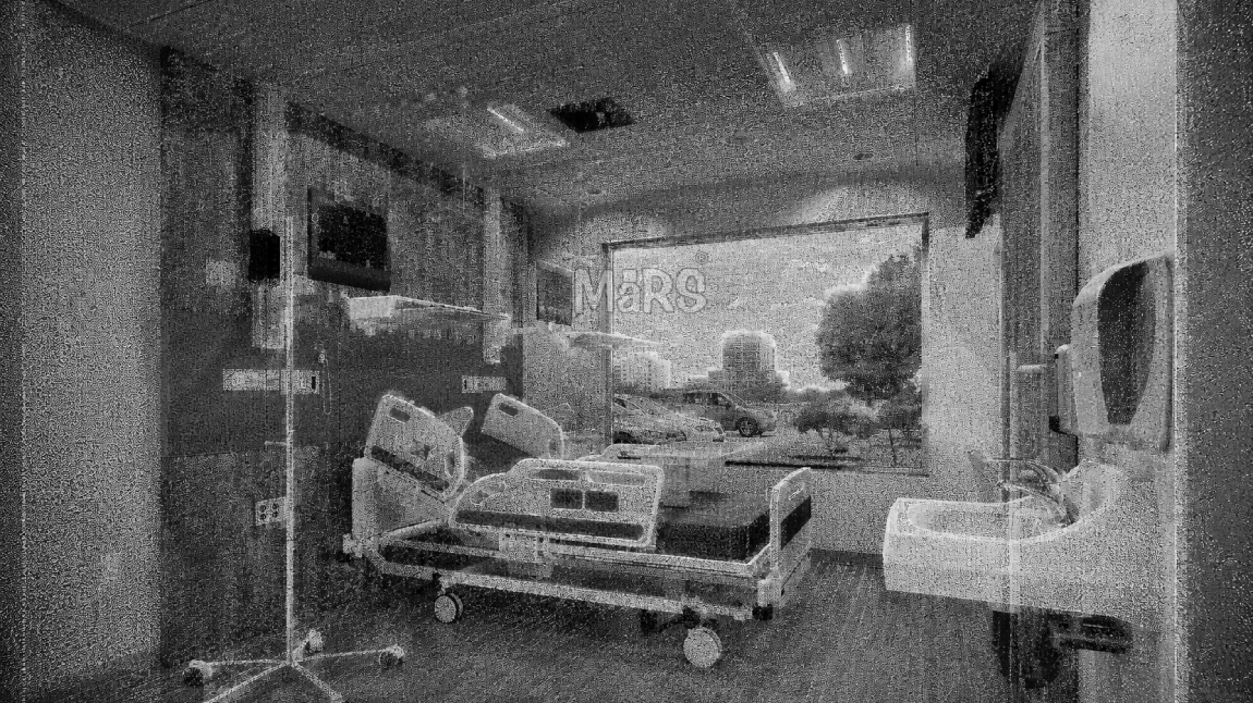
A hospital trust needed to replace an aging plant room and reroute several service risers, but the only way to plan the work safely was to know exactly what was running through the ceiling voids above three live wards.
We modeled ducts, pipes, cable trays and supports above the wards from scan data captured during scheduled ceiling access, then ran a clash test against the proposed new routing so the installation team knew every conflict before mobilising.
Survey and modeling completed entirely around the live clinical schedule
Resolved on paper before installation began
From first scan to a coordinated, clash checked MEP model
"The model saved us a shutdown. Three clashes in the riser would have cost us a weekend of rework. They found all of them first."
Straight answers so you can scope your project with confidence.
Only where the scanner could see them. We plan the survey with your facility team so tiles are lifted in agreed locations. Anything not scanned is marked as unverified rather than guessed.
At LOD 350 and above, yes. They matter more than most people expect because they take up the exact space where new services usually want to run.
We model both the pipe and the insulation outline where it is visible, since the outer dimension is what governs clearance on site.
Yes. Systems are set up with the correct Revit system types and naming so Navisworks clash rules work without manual regrouping.
Yes. At LOD 400 we include fittings, valves and connection detail suitable for spool drawings and off site fabrication.
Most clients bundle two or three of these to keep one team accountable for the whole scope.
Guides and technical notes from our BIM engineers. Links go live as new posts are published.
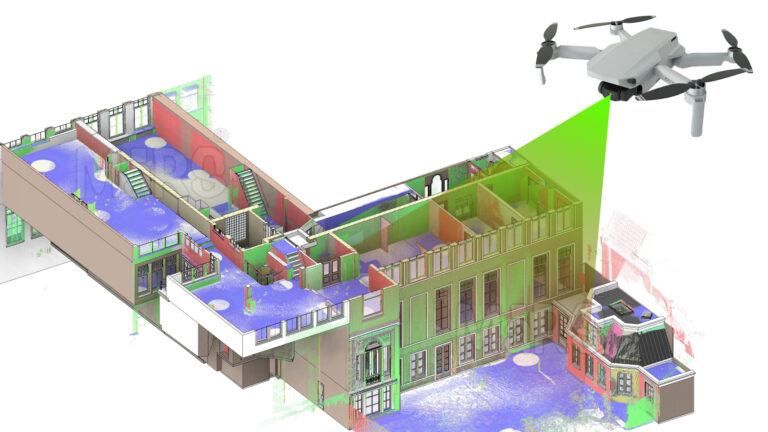
Learn how AI and LiDAR support urban planning, smart mobility, mapping, and data-driven city development with real-world applications.
Read article
Explore how Leica RTC360 supports fast site capture, accurate point clouds, and reliable Scan to BIM workflows for complex projects.
Read article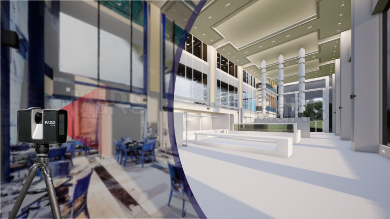
Learn how FARO scanning technology supports Scan to BIM conversion by capturing detailed site data for accurate BIM model development.
Read articleTell us the building, the area and the level of detail you need. We will come back with a fixed price and a firm delivery date within 24 hours.