Process piping model
Lines modeled with diameter, route, insulation outline, valves, flanges and support positions.
Shutdown windows are short and expensive. We model your process piping, structures and equipment as they are today, so new tie ins land first time and the plant restarts on schedule.
No obligation. Most quotes go out within 24 hours.
Process facilities change constantly. Lines get rerouted, valves get relocated, supports get added. P and IDs stay accurate but the physical layout drifts, and that drift is what breaks a tie in.
We model from scan data with pipe sizes, spool positions and support locations captured as built, and we work in the formats your engineering contractor already uses. Before fabrication starts, we usually run the model through clash detection to confirm every tie in is clear.
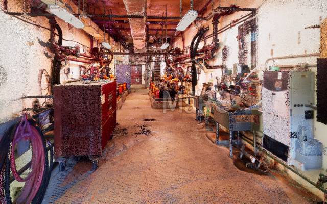
In a live plant, the cost of being wrong is measured in a closed line, not a change order.
This is what stops a spool arriving short on a shutdown that cost you a booked crew and a closed line.
Fittings, valves and connection detail suitable for spool drawings, not just a layout diagram.
Verified data reaches your fabricator with time to spare instead of the week before the plant goes down.
Clearance decisions depend on the outer face, not the nominal pipe size, so we model both.
Built for engineering contractors working to a shutdown clock.
Lines modeled with diameter, route, insulation outline, valves, flanges and support positions.
Vessels, pumps, tanks, heat exchangers and packaged skids placed in their measured positions.
Pipe racks, platforms, walkways, stairs and ladders modeled with real section sizes.
Every proposed connection point checked against the scan with a measured coordinate report.
Clash testing plus crane, lifting and maintenance access routes tested against the model.
Isometric drawings generated for fabrication where the project requires them.
Scoped area by area so you can start with the zones affected by the next shutdown.
| Scope item | What we deliver | Typical use |
|---|---|---|
| Piping | Routed lines with size, spec, supports and inline items | Tie in design and spool fabrication |
| Equipment | Vessels, pumps and skids with nozzle positions | Replacement and relocation planning |
| Steel | Racks, platforms and access structures | Load checks and modification design |
| Verification | Coordinate report on every tie in point | First time fit at shutdown |
Safety planning and access coordination are part of the job, not an afterthought.
We break the facility into zones and agree which lines, equipment and structures are in scope for each one.
Coverage is checked against the scope, with attention to congested areas where occlusion is likely.
Piping, equipment and steel are modeled by discipline against the registered cloud.
Proposed connection points are measured, reported with coordinates and issued for fabrication.
Clash and access studies are run, then the federated model is handed to your engineering team.
Programmes planned backwards from your window.
Tie in points measured and reported, not estimated.
Used to working around operating facilities.
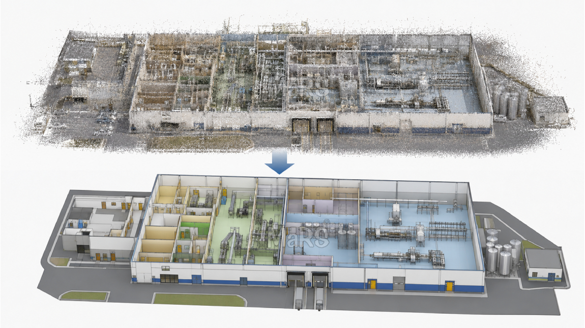
A food processing plant needed to tie new process lines into an existing piping network during a single 96 hour shutdown window, with no room for a tie in to be wrong once fabrication started.
We modeled the existing piping and steel to LOD 400 from scan data, measured all 62 proposed tie in points against the registered cloud and issued a coordinate report the fabricator used directly for spool drawings.
Every one confirmed within tolerance before fabrication began
The fabricator returned zero spools during the shutdown
Plant restarted on schedule with no extension
"Sixty two tie ins, every one within tolerance. Our fabricator did not send a single spool back. That has never happened before on a shutdown this size."
Straight answers so you can scope your project with confidence.
Both. Revit suits buildings and mixed facilities, Plant 3D suits process heavy scopes with spec driven piping. We will recommend the right one for your project and can deliver IFC either way.
Yes, where the model is built with a piping specification applied. We confirm the spec at the start so isometrics can be generated cleanly rather than drafted by hand.
Congestion is where occlusion hurts most. We identify shadowed zones during the scan review, request supplementary scans where needed, and mark anything modeled from partial data.
Yes, and it is one of the most valuable things we do. Each tie in gets a measured coordinate, a photo reference and a tolerance note, which is what stops a spool arriving 40 mm short.
Yes. Insulated lines are modeled with both the pipe and the outer insulation dimension, because clearance decisions depend on the outer face.
Most clients bundle two or three of these to keep one team accountable for the whole scope.
Guides and technical notes from our BIM engineers. Links go live as new posts are published.
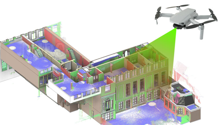
Learn how AI and LiDAR support urban planning, smart mobility, mapping, and data-driven city development with real-world applications.
Read article
Explore how Leica RTC360 supports fast site capture, accurate point clouds, and reliable Scan to BIM workflows for complex projects.
Read article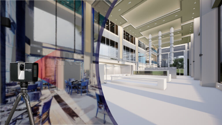
Learn how FARO scanning technology supports Scan to BIM conversion by capturing detailed site data for accurate BIM model development.
Read articleTell us the building, the area and the level of detail you need. We will come back with a fixed price and a firm delivery date within 24 hours.