Structural frame model
Columns, beams, braces, slabs, walls and foundations placed against the cloud with true section sizes.

Concrete frames that have moved, steel that was field modified, slabs that are anything but level. We model what is really there so your structural analysis starts from measured fact.
No obligation. Most quotes go out within 24 hours.
A column that sits 40 mm off grid or a slab that dips 25 mm across a bay changes what you can safely do. Those numbers rarely appear on legacy drawings, but they always appear in scan data.
Our structural modelers come from engineering backgrounds. They read the cloud for section profile, deflection and connection type, and they flag anything that looks like it needs an engineer to walk the site. Once the frame is modeled, it feeds straight into clash detection and coordination against the rest of the building.
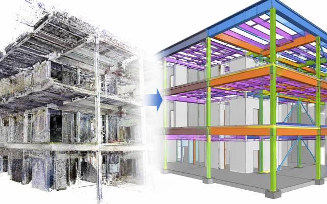
Drag the handle to compare the scan against the finished model
This is not a BIM technician tracing a point cloud. Structural work runs through people who read frames for a living.
Section sizes are measured directly from the point cloud and matched to catalogue profiles, not estimated from an old drawing.
A colour mapped drawing of floor level variance across every bay, at no extra cost and no extra ask.
Not a generalist BIM technician. Someone who has designed frames reviews the model before it is released.
We test the export path early so any mapping issue surfaces in week one, not at handover.
Built for the engineer who has to sign the calculation.
Columns, beams, braces, slabs, walls and foundations placed against the cloud with true section sizes.
A record of every section profile measured from the scan, with a confidence note where access was limited.
A colour mapped drawing showing floor level variation across each bay, which drives screed and finish decisions.
Baseplates, cleats, gussets and welded connections modeled where the scan resolution supports it.
An analytical layer set up so the model can be pushed into your structural analysis package.
Framing plans, elevations and sections generated from the model on your titleblock.
Steel, concrete, timber and masonry. Mixed frames are normal for us.
| Scope item | What we deliver | Typical use |
|---|---|---|
| Concrete frame | Columns, beams and slabs with measured sections | Load assessment and retrofit design |
| Steel frame | Profiles matched to catalogue sections plus bracing | Strengthening and extension works |
| Slab survey | Level readings mapped across the floor plate | Screed, flooring and equipment setout |
| Connections | Baseplates, cleats and welds where scan resolution allows | Detailed structural checks |
Engineering review is built into the process, not added at the end.
Structural grids are derived from the scanned column centres and compared against any legacy drawings you hold.
Columns and main beams are placed first, with each section profile measured from the cloud.
Slabs, bracing, secondary framing and openings are added, along with visible connection detail.
Level and alignment variance is mapped and flagged so your engineer sees the outliers immediately.
A structural engineer reviews the model before release, then it ships with drawings and reports.
Reviewed by people who have designed frames.
Profiles measured, not guessed from a drawing.
Analytical layer prepared for your software.
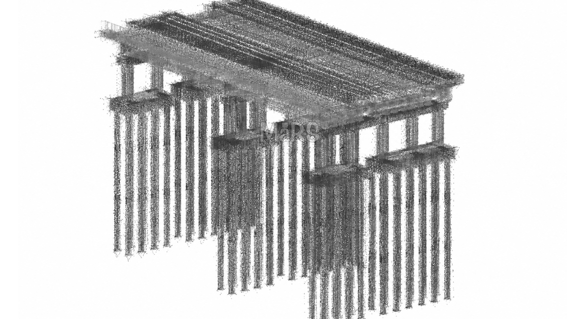
An automotive manufacturer needed to confirm whether an existing steel frame could support a new production line and overhead crane system, but the original structural drawings had been lost decades earlier.
We modeled the full steel frame from scan data with true measured section sizes, mapped slab level deviation across the whole hall and flagged three columns showing signs of historic overload for the client structural engineer to inspect.
Columns, beams and bracing measured directly from the point cloud
For engineer inspection before the new line was approved
From scan data to a signed off analytical model
"Their slab deviation map told us more about the real condition of that hall than any drawing we had."
Straight answers so you can scope your project with confidence.
For exposed steel and concrete, yes. We measure the profile directly from the cloud and match it to catalogue sections. Where members are encased or hidden, we mark them as assumed and recommend targeted opening up.
Reinforcement is not visible to a laser scanner. We can model rebar from GPR scan data or from record drawings if you supply them, and we mark the source clearly in the model.
Yes. We prepare the analytical model in Revit and export to formats used by common analysis packages. We will run a test export early so any mapping issue is caught in week one.
We model the encasement outline and note the assumed steel section inside. If exact sizes are critical, we advise where to open up so the model can be confirmed.
No. It comes as standard with every structural scan to BIM project because it is one of the most useful things the scan data can tell you.
Most clients bundle two or three of these to keep one team accountable for the whole scope.
Guides and technical notes from our BIM engineers. Links go live as new posts are published.
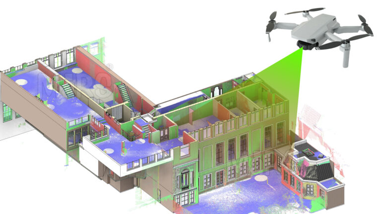
Learn how AI and LiDAR support urban planning, smart mobility, mapping, and data-driven city development with real-world applications.
Read article
Explore how Leica RTC360 supports fast site capture, accurate point clouds, and reliable Scan to BIM workflows for complex projects.
Read article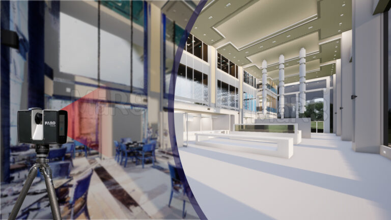
Learn how FARO scanning technology supports Scan to BIM conversion by capturing detailed site data for accurate BIM model development.
Read articleTell us the building, the area and the level of detail you need. We will come back with a fixed price and a firm delivery date within 24 hours.