
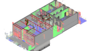
LiDAR Scan to BIM integrates high-resolution laser scanning with BIM modeling to capture and represent existing built environments with exceptional geometric accuracy. It begins with the collection of spatial data using LiDAR technology, which emits pulsed laser signals to generate millions of 3D coordinates, forming dense point clouds. The datasets are aligned to project-specific coordinate systems and transformed into parametric, object-based models. This process occurs within BIM platforms like Revit typically adhering to LOD 300–500 standards.
The application of this service extends beyond surface-level documentation. It provides a verified spatial foundation for detailed coordination, prefabrication, clash detection, and constructability reviews through Lidar Scan to BIM Services. It is valuable in retrofit-heavy environments such as industrial plants, heritage buildings, and healthcare facilities, where legacy conditions, undocumented installations, or structural deviations must be captured with precision before any design or construction activities proceed.
This workflow enables faster turnaround on RFIs, fewer site revisits, and tighter integration with 4D/5D schedules, cost plans, and asset databases. From preconstruction planning to facility handover, It delivers a data-rich model that drives downstream value for architects, engineers, contractors, and FM stakeholders alike.
How LiDAR Scan to BIM Works Process Overview
It is executed through a tightly controlled workflow, typically led by a BIM coordinator and scanning specialist working in tandem. It starts by defining not just the scope but the intent of use coordination, prefabrication, FM integration, or regulatory compliance. Scanning decisions are shaped by project complexity, material reflectivity, environmental constraints, and required modeling tolerances. The result must serve as both a geometric reference and a data-rich asset embedded with metadata aligned to the BIM Execution Plan.
- Field-to-BIM Workflow Essentials: LOD & BEP Definition: LOD 350+ requires not just geometry but fabrication-level detail. BEP alignment ensures naming conventions, classification systems, and COBie parameters are included from the start.
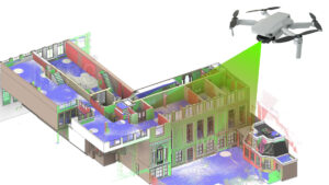
- Scan Strategy: Terrestrial tripod-based LiDAR, like Leica RTC360 , FARO Focus is deployed for interior architectural and MEP detail; SLAM-based mobile scanners fill gaps in congested or GPS-denied areas.
- Device Setup & Coverage: Scan density and overlap (minimum 30–40%) are planned to minimize occlusion and surface noise, especially near pipe clusters or ceiling voids. Scanner positioning is coordinated with access logistics and safety protocols.
- Registration & Control Points: Cloud-to-cloud alignment is supported by survey-grade control using total station benchmarks or GPS georeferencing, depending on project needs. Misalignment tolerance is kept below 5 mm for LOD 350+ workflows.
- Point Cloud Optimization: Raw scans are cleaned of noise, unified in Recap Pro or Cyclone REGISTER, and structured for modeling. Region segmentation may be used to isolate floors, trades, or asset groups.
- Model Authoring: Modelers interpret point clouds using Revit, Rhino, or Plant 3D. Model geometry is traced to match scan accuracy, not design assumptions.
- QA/QC Cycle: Deviation analysis is run in Navisworks or Verity to confirm the model aligns to the scan within project-defined tolerances (typically 5–10 mm for non-structural elements, <5 mm for load-bearing or alignment-critical zones).
Pro Tip: Match scan resolution, overlap ratio, and station density to the required model LOD, tolerance band, and asset complexity.
LiDAR Scan to BIM is not a linear pipeline; it’s an iterative process where scanning decisions affect modeling workload and vice versa. High-skill teams calibrate scan granularity to balance file weight with model fidelity, ensuring that only necessary geometry is modeled while preserving technical integrity. The output is a federated, coordination-ready model that mirrors site reality and supports downstream uses like clash detection, 4D phasing, asset tagging, and long-term facility optimization.
Core Deliverables of LiDAR Scan to BIM
As-Built BIM Models (LOD 300–500)
Discipline-specific models built from scan-aligned geometry, structured for trade coordination, fabrication, and spatial validation.
Scan-Registered, Georeferenced Point Clouds
High-density point clouds cleaned, indexed, and registered to local/site coordinate systems for traceable modeling workflows.
Dimensional Deviation & Tolerance Reports
Automated comparisons between scan geometry and design intent with color-coded deviation maps within ±3–10 mm tolerances.
Clash-Detection-Ready Federated Models
Multi-trade models generated with spatial precision, pre-clash tested for structural, MEP, and envelope alignment.
LOD-Tuned Quantity Take-Off Models
Element-based quantities extracted from LOD 350+ models using classified BIM objects linked to cost estimation platforms.
FM-Enabled Digital Twin Models
Asset-tagged models with COBie attributes and system hierarchy, ready for CMMS/CAFM integration and lifecycle analytics.
Where It Fits in the Construction Lifecycle
Preconstruction Phase
It establishes an accurate spatial baseline for design decisions, retrofit feasibility, and scope validation. It enables early-stage trade coordination, adaptive reuse modeling, and constraint mapping in complex environments such as hospitals, data centers, or heritage sites where legacy documentation is incomplete or unreliable.
Construction Phase
Field-verified BIM models are used for geometric validation, tolerance checks, and progress monitoring. Teams perform real-time deviation analysis between installed elements and design intent, feeding updates into 4D schedules and prefabrication workflows. This ensures alignment of structural and MEP systems before critical path impacts occur.
Post-Construction
The federated model is handed over with asset metadata, zone definitions, and COBie-linked parameters. Integrated with CMMS, CAFM, or digital twin platforms, the model supports space utilization tracking, preventive maintenance scheduling, and system performance monitoring across HVAC, fire protection, and electrical networks.
Industry Use Cases and Sector Applications
Commercial Fit-Outs: Scan-to-BIM is used to generate construction-grade as-built models of congested ceiling voids and service corridors, supporting multi-trade coordination and modular assembly of pre-engineered MEP systems. Site tolerances are captured to within ±5 mm to mitigate downstream RFIs and change orders in fast-track interiors.
Healthcare Facilities: Hospitals require exact spatial modeling of MEP routes around infection control zones, negative pressure rooms, and radiation-shielded enclosures. LiDAR-based models ensure medical gas lines, HVAC ducts, and cabling conform to health authority clearances, with accurate hanger positioning and clash-free penetrations.
Operational Industrial Plants: In brownfield environments, phased LiDAR scans capture piping geometry, steel framing, and floor-level machinery with minimal downtime. The BIM output supports isometric extraction, laser cutting, and prefabricated spool design while maintaining clearance maps for shutdown execution and fire-risk assessments.
Heritage & Complex Geometry Structures: For conservation-grade documentation, LiDAR is applied to map warped stonework, non-orthogonal walls, and façade reliefs with sub-centimeter fidelity. The resulting mesh-to-BIM models are used to simulate structural interventions, seismic retrofits, or moisture protection strategies without compromising heritage integrity.
Transportation & Infrastructure: LiDAR is deployed in multi-modal hubs (e.g. airport terminals, underground stations) for capturing ceiling clearances, passenger flow paths, and back-of-house utility corridors. Resulting BIMs feed into phased expansion modeling, crowd simulation tools, and MEP systems separation for critical infrastructure redundancy.
Civil & Geotechnical Applications: In terrain-heavy sites, mobile and drone-mounted LiDAR scans are used to model soil volumes, cut-fill zones, retaining wall interfaces, and stormwater channels. Resultant BIM-Civil models are integrated into Earthworks planning, deformation tracking, and subsurface utility conflict analysis.
Benefits of LiDAR Scan to BIM Services
- Field-verified prefabrication workflows by capturing exact hanger positions, duct offsets, and pipe centerlines
- Drives clash-free routing in ceiling voids, risers, and congested shafts using actual site geometry
- Supports tolerance-based deviation tracking between installed components and design models within BIM platforms
- Captures active sites like hospitals and plants without interrupting operations or requiring shutdowns
- Prevents undocumented condition errors in retrofit scopes by modeling real-world geometry before redesign
- Aligns 4D/5D simulations with verified field conditions for reliable phasing, sequencing, and cash flow planning
- Documents brownfield assets with undocumented MEP, slab penetrations, and structure-to-equipment relationships
- Delivers FM-ready Revit models with COBie properties, asset IDs, spatial zones, and linked O&M documentation
- Reduces repeat site visits for coordination, verification, and drawing markups through high-density point clouds
- Integrates with Navisworks, BIM 360, and other CDEs to support real-time coordination using scan-aligned geometry
Challenges and Limitations
- Minor alignment drift across scan stations can compound into measurable deviation especially in long corridors or vertically stacked utility zones.
- Ceiling-mounted services and overhead clashes can block laser lines, leaving scan voids that require manual modeling or second-pass scans.
- Teams often spend time modeling non-critical elements like conduit junctions, fire alarms that are irrelevant to the project’s coordination goals.
- Excessive scan resolution in low-detail areas inflates point cloud size without improving modeling efficiency slowing downstream workflows.
- Mobile SLAM units can lose spatial accuracy during extended walkthroughs in large plants or basements unless regularly re-synced to known control points.
- Native Revit tools struggle with modeling curved, sloped, or warped geometry from heritage or cast-in-place concrete structures requiring Rhino or mesh processing.
- Point cloud data alone may not clearly distinguish between structural elements and mechanical assemblies without onsite clarification.
- Late-stage changes in naming conventions, classification schema, or asset codes create rework in both Revit models and COBie deliverables.
Quality Parameters and Project Gains
Quality in LiDAR Scan to BIM delivery depends on measurable accuracy, data traceability, and workflow alignment with project intent. Each scan-to-model output is validated through dimensional tolerance checks, metadata compliance, and model usability across fabrication, coordination, and asset management stages. Gains are not just technical but operational fewer delays, clearer sign-offs, and better control over construction variables.
Key Parameters and Gains
- Geometric deviation tolerance kept within ±3 mm for MEP clash zones and ±5 mm for structural shells
- RMS error across scan stations monitored and documented under 2.5 mm using fixed control targets
- LOD matrices enforced during QA to verify scope-specific detail avoiding unnecessary modeling of low-priority assets
- Automated rule-based model audits using Solibri or Dynamo to flag naming, hosting, and classification inconsistencies
- Fabrication accuracy improved by extracting verified hanger, bracket, and insert coordinates directly from the model
- Clash issue volume reduced by 80–90% pre-construction through geometry that reflects real field conditions
- Faster model approvals due to traceable scan origins, annotated model views, and metadata-backed validation
- Asset data handoff improved with zone-tagged models structured for direct CMMS or CAFM integration
Why Your Project Needs It
It is a precision-based workflow that converts existing conditions into data-rich, coordination-ready models aligned with fabrication, construction, and FM outcomes. It eliminates guesswork by capturing site-verified geometry and linking it to BIM logic, helping teams reduce RFIs, avoid scope gaps, and deliver models that reflect true field constraints. On projects involving retrofit upgrades, phased construction, live environments, or BIM-led delivery mandates, it adds measurable control over tolerance, sequencing, and asset integration. With the right scope definition and QA processes, It becomes a core enabler of reduced rework, faster coordination cycles, and reliable digital handover.


Recent Comments