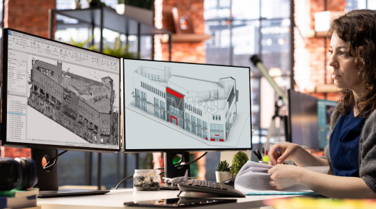
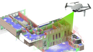
Tight construction schedules, high-density MEP systems, and increasing use of prefabrication demand precise site intelligence at every stage of execution. Point cloud modeling services have become critical for converting scanned site data into intelligent BIM models tailored for coordination, fabrication, and installation. These services play a pivotal role in capturing real-world conditions and translating them into usable digital assets on projects involving adaptive reuse, vertical expansions, or phased renovations.
Revit-ready outputs refer to models that include native Revit families, embedded parameters, trade-specific segmentation, and alignment to project grids and control points. These models integrate directly into coordination platforms, support quantity extraction, and allow installers to rely on digital layouts with confidence. With proper worksets, LOD structuring, and system logic built in, such models streamline decision-making for general contractors, MEP trades, and façade specialists alike.
Field-driven modeling is rapidly becoming the default for large-scale and complex construction. From sleeve coordination before slab pours to bracket positioning on irregular façades, Revit-ready BIM models derived from point clouds enhance accuracy, reduce coordination cycles, and support early-stage fabrication planning. This approach ensures that site conditions and design models stay in sync from scan to install.
What Is Point Cloud to BIM?
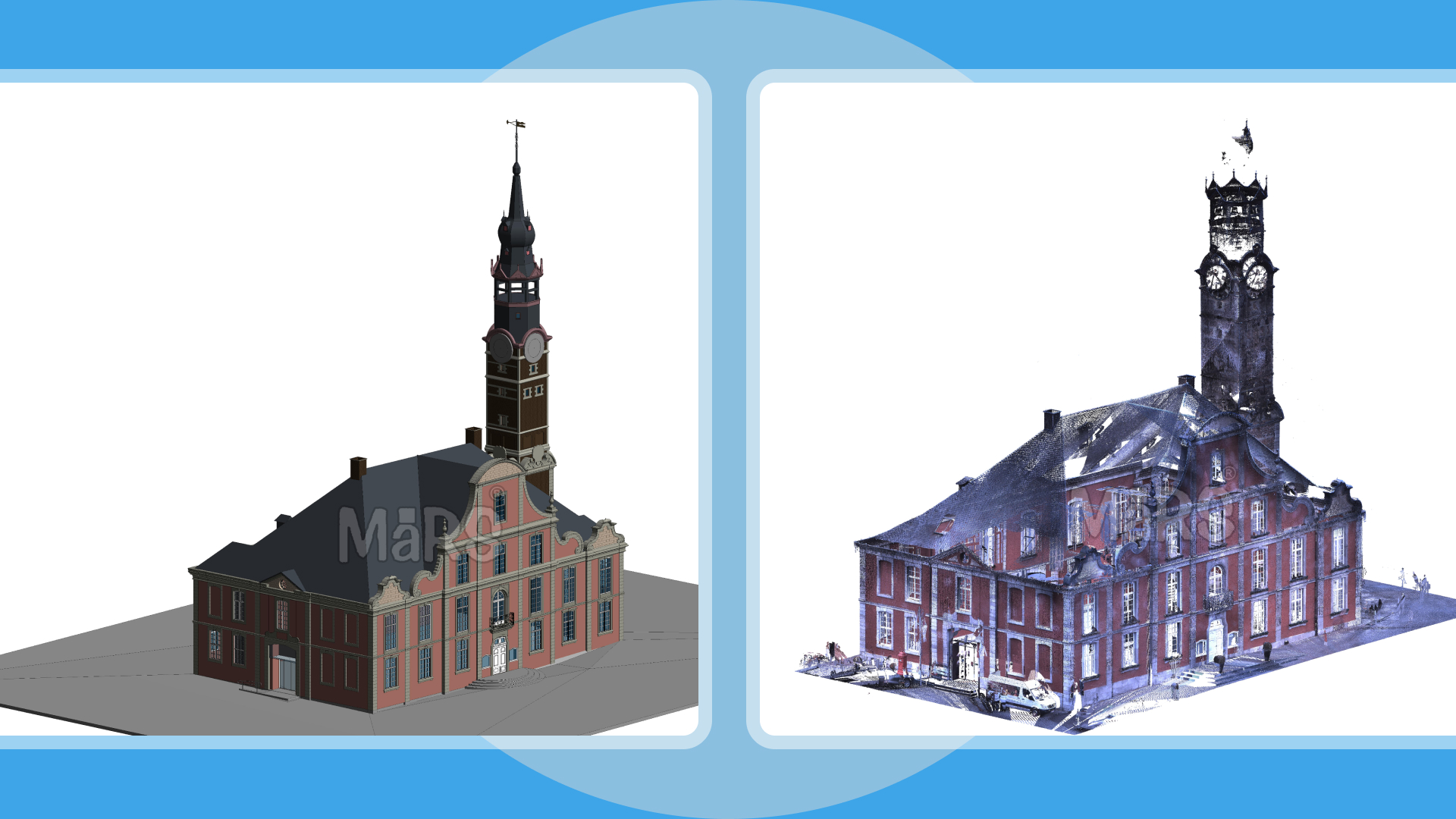
Point Cloud to BIM is a precision-driven modeling workflow that translates spatial data from LiDAR, drone, or mobile scanners into discipline-specific Revit environments used for direct coordination, fabrication, or field layout. Unlike generic 3D modeling, this process begins with registered point clouds often exceeding 1 billion data points per zone aligned to control networks and construction grids. Formats such as .e57, .rcs, and .ptg are selected based on scanner type, software pipeline, and desired resolution in shadowed or obstructed zones. Once referenced into Revit or Recap, geometry is reconstructed selectively, prioritizing coordination-sensitive areas like soffit transitions, service zones, and slab edges around core walls.
The objective is extraction of constructible geometry aligned to installation tolerances. Structural elements are modeled to support rebar shop detailing; MEP routes are verified against hanger zones and embed locations. Slab penetrations are captured with centerline accuracy for sleeve layout. Modeling uses native Revit system families and worksets segmented by trade, pour, or prefab scope. Final outputs conform to BIM Execution Plans and are structured for seamless use in platforms like Navisworks, Assemble, or BIM 360, supporting downstream workflows including 4D sequencing, clash detection, and field layout integration.
Core Point Cloud to BIM Services
Architectural Modeling:
Architectural modeling from point clouds focuses on accurately defining core building geometry like walls, slabs, doors, windows, and façades. It aligned with grid systems and level datums. Outputs support interior fit-outs, façade retrofits, and permit-level documentation with model elements structured using native Revit categories and shared parameters.
Structural BIM Modeling:
Structural modeling captures beams, columns, slabs, and foundation systems, whether cast-in-place or precast, to match structural tolerances and load-path continuity. Revit models are built for structural coordination, embedded plate alignment, and detailing integration, supporting both design validation and construction documentation.
MEP & HVAC Modeling:
MEP models derived from scanned information include ducts, pipes, cable trays, and equipment, with a focus on clearance zones, sleeve positions, and hanger coordination. Outputs are created using discipline-specific system families, facilitating clash detection, prefabrication planning, and installation-ready documentation in congested ceiling spaces.
Revit Family Creation:
Custom Revit families are developed for non-standard components like façade brackets, rooftop equipment pads, or field-measured access hatches. Each family is parametric, classified, and embedded with performance data to streamline repetitive modeling and accurate takeoff generation.
2D Drawings & Documentation:
Plans, sections, elevations, and RCPs are extracted directly from the Revit model, layered per drafting standards and dimensioned for site usability. These drawings are used for layout validation, shop drawing production, and coordination markups, supporting both digital workflows and on-site execution.
From Scan to Construction-Grade Revit Output
Revit models developed from scanned data are structured around field-executable scopes prioritizing geometry tied to trade tolerances, sequencing logic, and installation critical paths. Instead of blanket modeling, focus is placed on penetrations through post-tensioned decks, slab edge offsets, steel-to-concrete interface zones, and hanger coordination envelopes. Elements are built using discipline-specific Revit templates with shared parameters, embedded system logic, and coordinated control points to support layout verification and prefabrication release. Models are packaged per pour sequence, MEP zone, or crane pick area, with worksets and linked files organized to match construction phasing. Geometry is simplified only where spatial tolerances allow, ensuring model fidelity in areas like riser shafts, corridor ceilings, and structural transfers, where deviation from site conditions can directly affect buildability and lead time.
Deliverables You Can Expect
- LOD 100–500 BIM Models
- As-Built Revit Models
- Trade-Separated Coordination Models
- Custom Revit Families
- 2D CAD and Shop Drawing Outputs
- Quantity Takeoffs and Material Schedules
- Clash Detection Reports
Use Cases That Support Field Execution
Sleeve & Embed Coordination
Revit-modeled penetrations derived from scan-verified slab geometry used for pre-pour sleeve layout, minimizing core drilling and misalignments in congested service zones.
As-Built Verification for Trade Sign-Offs
Alignment of point cloud overlays with coordinated Revit models to validate installed MEP systems before sign-off, reducing RFIs and handover delays.
Façade Bracket and Anchor Layouts
Anchor positions modeled from as-scanned slab edge and backup wall conditions, ensuring alignment with structural embed plates during façade system installation.
Crane Lift Path Validation
Revit-integrated geometry used to simulate crane swing paths, pick zones, and load clearances in proximity to built structures or temporary works.
Selective Demolition and Tie-In Planning
Field conditions modeled from scans to identify structural interfaces, expansion joints, and slab cut zones for precise demolition phasing and retrofit tie-ins.
Accuracy, Documentation, and Technical QA
Precision in point cloud to BIM workflows hinges on tightly controlled registration protocols and element-level deviation tracking. Each modeled penetration, hanger zone, or anchor point is cross-validated against the raw data using RMS thresholds defined per trade, typically ±10 mm for MEP zones and ±5 mm for structural interfaces. Deviation reports include color-coded delta visualizations, exported alongside the Revit model, enabling construction managers to review variances before issuing for installation. Control points are embedded as reference planes and shared parameters within the model, mapped to total station layout coordinates to streamline field verification. Additionally, metadata on scan resolution, occlusion zones, and scanner positioning is recorded in the deliverable set, providing traceability for QA/QC audits. This technical documentation becomes especially critical when validating prefabricated assemblies or coordinating slab penetrations across multiple trades.
Process Workflow
Data Collection
Gather registered point clouds and project documentation, including control points, level plans, and scope drawings.
Scan Alignment
Align point cloud data to the project coordinate system and vertical datum using control networks or survey benchmarks.
Trade Scope Segmentation
Isolate modeling zones by discipline, floor, or pour sequence to streamline coordination and delivery packaging.
Revit Modeling
Build architectural, structural, and MEP models in Revit using native families, shared parameters, and project-specific templates.
Deviation Analysis & QA
Perform tolerance checks between modeled elements and the point cloud, generating deviation reports and visual overlays.
Internal Review
Conduct model health checks, naming validation, and workset audits to ensure compliance with BEP and modeling standards.
Client Feedback Loop
Share preliminary deliverables for trade review, incorporating redlines or markups before final release.
Final Export & Handover
Deliver models in .RVT, .NWC, .DWG, and IFC formats, along with supporting documents like clash reports and deviation maps.
Common Pitfalls in Scan-to-Revit Delivery
- Modeling MEP systems without accounting for field-verified hanger zones, leading to unbuildable layouts during installation
- Embedding scan-aligned geometry without aligning to project grid or survey control, disrupting prefabrication layout and robotic total station workflows
- Using non-parametric placeholder families for critical components, breaking downstream fabrication schedules and BOM extraction
- Omitting cast-in elements such as embed plates and blockouts during modeling, requiring costly field rework post-slab pour
- Ignoring tolerance-driven modeling failing to differentiate between ±10 mm zones and ±2 mm zones
- Delivering unsegmented Revit models lacking linked trade structure, making Navisworks coordination and construction phasing unmanageable
- Misrepresenting sloped surfaces, ramps, or deck camber as flat planes, resulting in clashes during pipe rack or curtain wall installation
- Skipping deviation tracking between point cloud and model, leaving discrepancies unresolved during QA reviews or subcontractor approval cycles
Advantages of Outsourcing Point Cloud Modeling
- Trade-specific Revit outputs developed with embedded constraints, enabling direct import into fabrication software like SysQue, Trimble Fab, or Victaulic Tools
- Discipline-aligned modeling teams familiar with scope split logic—producing linked models per riser shaft, core zone, or MEP rack path to match construction staging
- Accelerated coordination cycles through availability of Revit-ready penetrations, hanger points, and anchor plates derived from verified scan zones
- Prefab-ready deliverables generated with real-world tolerance zones, ensuring duct/pipe spool packages fit within as-scanned spatial limits
- Teams equipped to process hybrid scan data (terrestrial + drone + mobile) for complex zones such as atriums, mechanical penthouses, or existing tunnel interfaces
- Deliverables structured with workset strategies aligned to federated model environments, allowing field engineers to isolate systems during layout
- Availability of audit trails scan-to-model deviation logs, family naming audits, and LOD matrices to support VDC sign-offs and subcontractor buy-in
- Capability to work under strict naming, phasing, and grid-control requirements in design-build, PPP, or IPD project delivery formats
Conclusion
Revit-ready point cloud models have become important tools for executing high-density, trade-intensive scopes where tolerance control and sequence precision drive success. These outputs enable the layout of penetrations before slab pour, validate prefabricated rack fit within actual site conditions, and ensure bracket locations align with as-built substrate geometry. By modeling only what is field-relevant with the right constraints, metadata, and coordination logic project teams eliminate guesswork in sleeves, embeds, and tie-ins. This shift transforms BIM from a coordination artifact into a direct enabler of construction execution, allowing GCs and subcontractors to make layout, fabrication, and installation decisions based on verified geometry. As field productivity and prefab adoption continue to rise, scan-based Revit modeling has become the operational baseline, not an added value.


Recent Comments