
Scan to BIM using photogrammetry provides construction teams with fast, high-fidelity digital models derived from actual site conditions. By capturing overlapping images through drones or handheld devices, photogrammetry reconstructs existing buildings, structures, and terrain with precision. These outputs feed directly into BIM platforms like Revit, enabling accurate planning, coordination, and construction modeling from the earliest stages.
Contractors and project managers increasingly rely on rapid, reliable data to make early design decisions, resolve clashes, and support prefabrication. Photogrammetry-based modeling addresses the demand for faster surveys across urban infill sites, brownfield developments, and occupied buildings. Reduced need for manual measurement or complex scanning setups makes this method ideal for fast-moving renovation, expansion, and retrofit projects.
Construction firms apply photogrammetry scan to BIM modeling workflows across a wide range of field conditions, from commercial fit-outs to hospital retrofits and heritage restorations. Drone-based imaging captures rooftop units, external façades, and vertical zones without scaffolding or shutdowns. These models enhance MEP coordination, facilitate approvals, and support schedule-driven execution through visual clarity and dimensional accuracy.
Why Quick and Accurate Surveys Matter in AEC
Construction teams face increasing pressure to deliver projects on constrained sites where sequencing, logistics, and access must be tightly coordinated. Urban infill buildings, vertical expansions, and adaptive reuse projects often start with incomplete or outdated site documentation. Photogrammetry-based BIM modeling gives general contractors and survey teams a faster way to generate detailed existing-condition models that support early trade coordination, temporary works planning, and preconstruction logistics.
Real-time decision-making on active job sites requires more than static drawings or occasional scans. Site managers now depend on regular visual and dimensional updates to validate pour sequencing, align MEP inserts, and release prefabricated assemblies. Photogrammetry delivers image-rich, geometry-aligned data that can be integrated into weekly coordination meetings, RFIs, and subcontractor planning workflows, bridging the gap between field conditions and coordinated BIM environments.
What is Photogrammetry Scan to BIM?
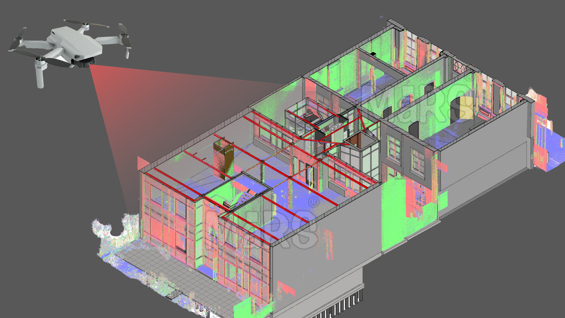
Photogrammetry Scan to BIM is a process that starts with capturing high-resolution images of the project site via drones or site cameras and ends with a data-rich 3D model built inside a BIM environment. These images, when processed through specialized software, generate dense point clouds that represent real-world geometry. Once the point cloud is cleaned and aligned, BIM specialists model architectural, structural, and MEP elements using platforms like Revit, ensuring that models reflect actual site conditions and are aligned to the project’s required LOD.
On active construction sites, this workflow supports layout planning, coordination checks, and field validation without interrupting work. Drones equipped with RTK/PPK GPS and high-resolution cameras can quickly capture entire rooftops, façades, and structural cores with minimal labor. Processing tools such as Pix4D, ReCap, and RealityCapture convert image sets into point cloud files like .rcs or .e57, which integrate directly into BIM workflows for design, clash detection, and fabrication planning.
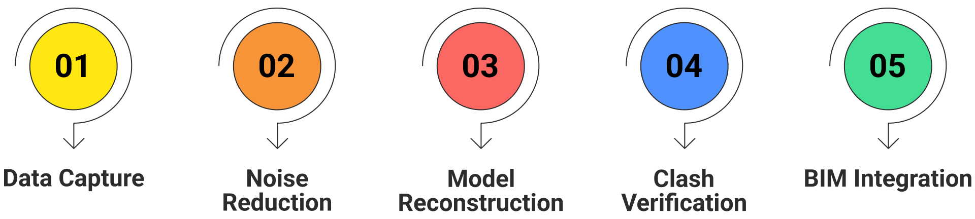
Image capture through drones or site-mounted cameras
- Point cloud generation from overlapping images using photogrammetry software
- BIM modeling based on point cloud data using Revit, Navisworks, etc.
- Hardware: Drones, RTK/PPK GPS, high-res cameras
- Software: Pix4D, RealityCapture, Autodesk ReCap
- Point cloud output formats: .rcs, .rcp, .e57
- Supports LOD-specific BIM creation for construction use

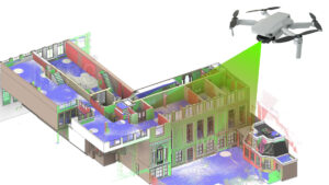
Drone-Based Photogrammetry for Site Reality Capture
Drone-based photogrammetry gives construction teams access to real-world site geometry without disrupting ongoing work. High-rise façades, rooftop equipment zones, cantilevered structures, and edge conditions are captured safely and accurately using automated flight paths. Drones equipped with RTK-enabled GPS and high-resolution cameras can scan large areas within a single site visit, making them ideal for early-stage documentation, structural validation, or façade condition modeling on congested job sites or mid-construction buildings.
For construction managers and BIM coordinators, drone-captured datasets improve both planning and execution. 3D site reality models support accurate quantity takeoffs, validate installed elements, and help avoid issues in steel or façade assembly sequencing. Hybrid drones that carry both photogrammetry cameras and LiDAR payloads extend this value further by capturing complex geometries around MEP risers, steel trusses, or plant infrastructure, delivering a complete digital context for field coordination and construction control.
Scan to BIM Workflow Tailored for AEC
Construction-focused photogrammetry starts with drone paths aligned to gridlines, slab levels, and structural points. This alignment supports core wall layout, façade anchoring, and MEP shaft positioning. Once processed, point clouds are filtered to isolate build-relevant geometry such as parapets, lift cores, and structural penetrations, allowing BIM teams to generate LOD-specific models for coordination and install sequencing. These models are validated against control benchmarks and used by trade contractors to align hanger layouts, verify tolerances, and issue markups during coordination meetings via BIM 360 or ACC platforms. This approach reduces layout errors, accelerates approval cycles, and integrates seamlessly into construction-driven modeling workflows.
Core Benefits of Photogrammetry-Based Scan to BIM
High Accuracy As-Built Documentation
Enables BIM teams to model slab edge offsets, beam pocket locations, and vertical riser positions tied to actual pour tolerances. Supports structural clash checks between embedded plates, MEP sleeves, and lift cores during early-stage fit-out. Captures discrepancies between drawings and on-site construction, allowing realignment before trade mobilization.
Time and Cost Efficiency
Eliminates the need for scaffolding or lift equipment just to validate elevations or façade anchor points. Reduces downtime between demolition and redesign by delivering model-ready data within 24–48 hours of capture. Shortens design-to-fabrication turnaround on retrofit projects by avoiding traditional resurvey delays.
Visualization and Stakeholder Collaboration
Gives site engineers and subcontractors visual overlays of anchor positions, ceiling grid clashes, or duct offsets before site work begins. Improves alignment between field redlines and digital models by offering image-verified context for issue markups. Used in weekly subcontractor meetings for installation planning, zone sequencing, and punch-list resolution.
Improved Safety
Prevents the need to access cantilevered edges, crane zones, or partially demolished areas just for measurement. Supports survey tasks from a safe perimeter, useful during early-stage site prep or unstable structures. Used to verify hard-to-reach rooftop zones or voids before waterproofing, MEP installation, or crane lifts.
Rich, Actionable Data
Delivers construction-phase models embedded with true site geometry, aiding exact hanger positioning and cut-out location validation. Used to cross-check against shop drawings, prefabrication models, or tolerance-critical packages. Enables tracking of installed conditions, helping facility teams transition into asset tagging and digital O&M workflows without remobilizing.
Targeted Use Cases in Construction Projects
Photogrammetry-based Scan to BIM supports a range of construction use cases where high accuracy and rapid data turnaround are important, from heritage façade capture and commercial retrofit modeling to MEP-intensive industrial environments. One such application was a data center project in Dallas, TX, delivered by Scan to BIM Solutions. The team generated a precise BIM model from point cloud data to aid renovation and facility management. Autodesk ReCap was used for scan processing, Revit for detailed architectural, structural, and MEP modeling, and Navisworks for system coordination. This model helped the client reduce risk during upgrades by avoiding service clashes and planning errors. Similar workflows are being used for franchise layout validations, hospital retrofits, rooftop HVAC upgrades, and progress monitoring on fast-track commercial builds. all demanding tight tolerances, visual clarity, and model-ready geometry to support execution.
Best Practices for Implementation
- Conduct pre-scan walkthroughs to identify access restrictions, safety zones, and capture priorities.
- Obtain necessary drone flight approvals for sites near airports, urban zones, or government facilities.
- Choose drones with RTK/PPK GPS to meet construction-grade accuracy for layout and coordination.
- Use photogrammetry for exterior and vertical zones; supplement with LiDAR for dense MEP interiors.
- Process raw image sets using Autodesk ReCap to clean, align, and export point clouds efficiently.
- Optimize point clouds by segmenting per trade or floor to reduce modeling time and file size issues.
- Build models in Revit aligned to project-required LOD, focusing on elements relevant to coordination.
- Use Navisworks for clash detection between structure, MEP, and architectural elements.
- Coordinate model reviews with field teams to capture redlines, penetrations, or layout shifts.
- Deliver Revit models with organized views, sheets, and parameters for facility use.
- Upload final models to BIM 360 or ACC for team-wide access, tracking, and collaboration.
Limitations and Mitigation Strategies
| Field Limitation | Mitigation Strategy for AEC Workflows |
| Incomplete rooftop capture due to equipment congestion | Plan drone flights during non-working hours or off-peak construction shifts to access congested zones |
| Inaccurate scan near façade scaffolding | Delay capture until scaffold removal or use ground-based photogrammetry to fill occluded vertical surfaces |
| Image blur from crane-induced turbulence | Use drones with gimbal stabilization and fly at controlled distances from crane paths |
| Misaligned structural grid in point cloud | Calibrate scans using known structural benchmarks (e.g., column centerlines, slab edges) before modeling |
| Model distortion over long elevations | Segment façade scans into logical bays and verify with dimensioned drawings or total station checks |
| Excess noise from reflective cladding | Adjust image exposure settings or use LiDAR for problematic material surfaces like glass or polished steel |
| Regulatory barriers in airport-adjacent sites | File coordinated airspace requests early; consider tethered drone systems or fixed-camera alternatives |
| Terrain variation affecting ground reference | Set RTK base stations at key levels and apply vertical correction during point cloud alignment |
Conclusion
Photogrammetry-led Scan to BIM is becoming important for AEC firms managing tight renovation timelines, retrofit complexities, and MEP-heavy project scopes. By enabling accurate, model-ready data from drone-captured imagery, contractors gain an early understanding of field conditions, crucial for clash-free installation, off-site fabrication, and schedule control. The approach proved critical in projects like the Dallas data center, where model precision directly impacted future upgrade paths and facility operations. As BIM deliverables evolve from design references to construction-ready tools, integrating photogrammetry workflows is no longer experimental. it’s a construction mandate for teams optimizing field performance and lifecycle reliability.


Recent Comments