Most construction handovers fail to capture the real complexity of built MEP systems. Facility teams often receive outdated PDFs, redlined drawings, or generic as-builts that don’t reflect on-site adjustments, rerouted conduits, or last-minute installations. This discrepancy isn’t just a documentation issue; it directly affects operational continuity, safety compliance, and long-term asset performance.
Facility managers are being held accountable for more than just maintenance; they’re expected to reduce energy use, plan system upgrades, and support sustainability reporting. Without reliable spatial and asset data for HVAC systems, electrical panels, fire lines, or vertical risers, those goals become guesswork. Technicians waste time tracing hidden ducts. Energy consultants model systems based on assumptions. Risk teams lack accurate layouts for emergency planning.
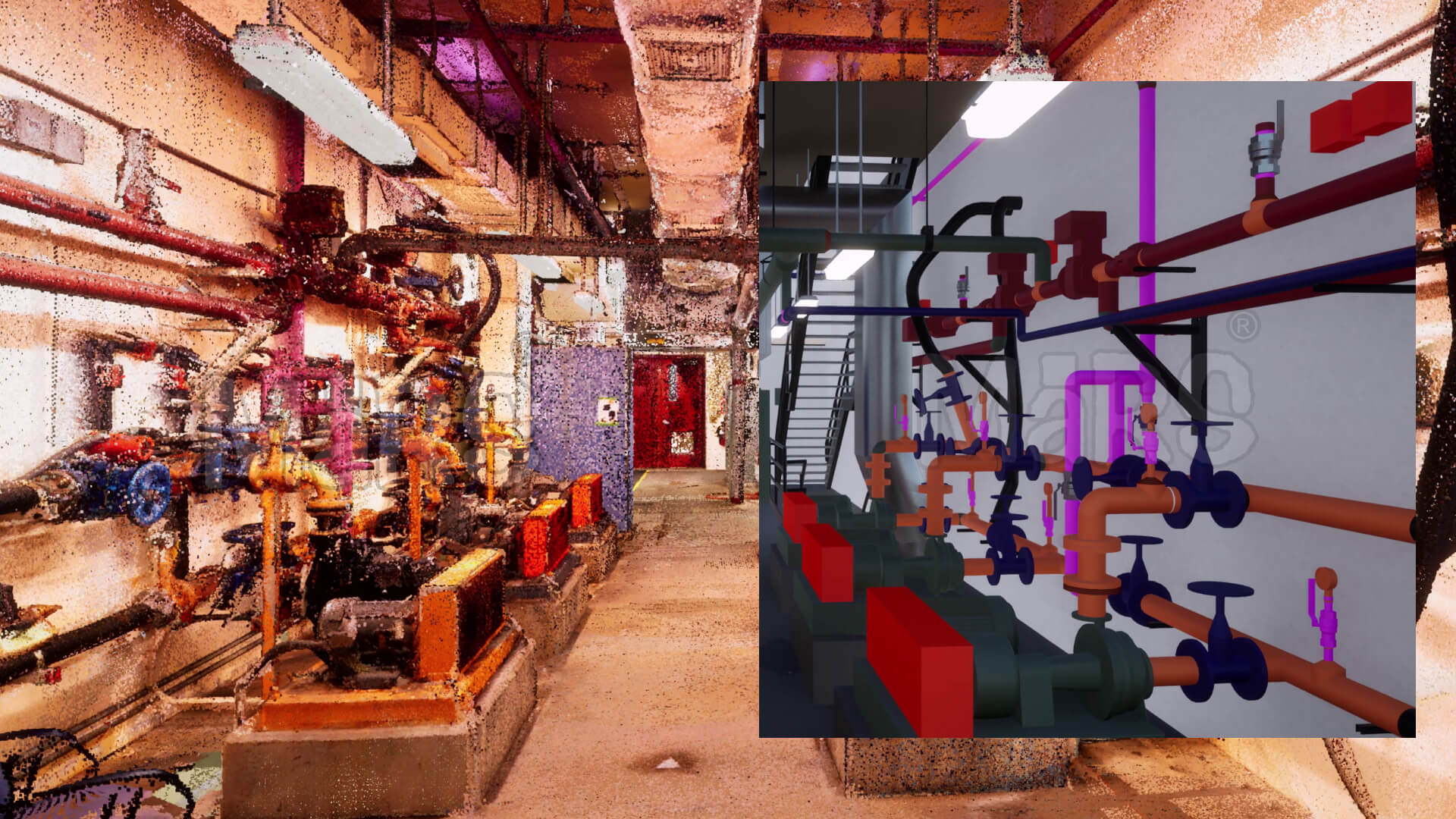
MEP Scan to BIM Services resolves this by capturing true field conditions through 3D laser scanning and converting them into coordinated, data-rich BIM models. These models document actual system locations, geometry, and specifications. creating a verified digital foundation for operations. Unlike static as-builts, this information is structured, updatable, and FM-ready, empowering facility teams to operate with clarity, efficiency, and control from day one.
Core Concepts and Technology Foundations
Building Information Modeling is a data-centric process that enables the construction and operations teams to work from a coordinated, spatially accurate model. For MEP systems, BIM offers more than 3D visualization. It enables system-level breakdowns, equipment tagging, clash-free routing, and lifecycle tracking. Mechanical rooms, riser shafts, ceiling plenums, and utility corridors are modeled with engineering precision, providing facilities teams with a clear view of service access zones, component dependencies, and performance-critical infrastructure. The model becomes a live asset that supports equipment scheduling, condition tracking, and asset replacement planning.
Scan to BIM technology captures existing MEP conditions with millimeter-level accuracy through high-speed laser scanning. The resulting point cloud is converted into a detailed BIM model that reflects the exact as-installed geometry of ductwork, pipe runs, cable trays, and service terminations. Facilities teams gain a digital twin that includes component-level data for shutoff valves, dampers, and distribution boards, structured for use in CMMS or CAFM platforms. This process eliminates reliance on outdated redlines or approximated layouts and replaces them with verified spatial intelligence that supports safe access, informed maintenance, and strategic facility planning.
What Makes MEP Scan to BIM Unique
MEP-focused Scan to BIM workflows are built around the complexity, inaccessibility, and operational criticality of building systems. These models target high-density service zones and require field-verified geometry aligned with real maintenance and operations constraints. The objective is not only to document components but also to enable facility teams to locate, analyze, and act on accurate system data within active buildings.
Specialized aspects that define MEP Scan to BIM:
- Focus on congested and limited-access infrastructure such as ceiling voids, riser shafts, mechanical basements, and utility trenches
- High-detail scanning of active systems like chilled water lines, VAV boxes, BMS panels, and med-gas valves that require precise field alignment
- Structured modeling that maps each component’s real-world connection trunk lines, branches, shutoffs, and isolation points rather than only geometry
- Asset intelligence embedded at the component level, including serial numbers, voltage ratings, flow capacity, and filter replacement intervals
- Delivered models structured for FM software use, often aligned to COBie, IFC, or Revit FM schemas for direct integration
- Field-validated models that support clearance analysis for maintenance zones, ladder access, and emergency isolation routes
Benefits to Facility and Asset Management

Digital Asset Repository
MEP Scan to BIM provides a location-verified digital model where all major systems HVAC branches, sprinkler loops, low-voltage cabling, and panel boards. These are mapped with service-level detail. Instead of referencing multiple drawing sets, facility teams can extract system paths, access requirements, and specifications from a single model environment. This becomes essential during condition assessments, system isolation, or third-party coordination.
Preventive Maintenance
Point cloud data captured at defined intervals allows operations teams to detect early-stage infrastructure changes, such as deflection in duct supports or mineral buildup in condensate lines. These indicators inform targeted interventions based on physical deviations, rather than time-based schedules. It becomes possible to prioritize critical assets based on location stress, usage intensity, and service constraints.
Equipment Replacement
Accurate placement of mechanical units, piping terminations, and electrical disconnects enables shutdown planning with minimal impact to surrounding systems. Teams can simulate the physical path for removal or replacement, evaluate clearance zones, and pre-identify access obstructions. This reduces reliance on intrusive field checks and lowers the risk of unanticipated delays during high-risk interventions.
Lifecycle Asset Management
Each asset modeled from scan data can be assigned with service life markers, warranty data, and system-level grouping. This enables asset managers to quantify replacement loads by room, floor, or zone. Facilities that manage large portfolios can use this data to prioritize capital expenditures based on operational load, environmental conditions, and usage history.
Operational Efficiency
MEP models developed from verified scan data reveal how mechanical and electrical systems impact air volume control, spatial headroom, and thermal zoning. Facilities teams can run spatial simulations to test airflow delivery paths, equipment proximity effects, and duct routing restrictions. These insights directly support efforts to recalibrate energy zones, downsize overprovisioned units, or free up ceiling plenum space.
Collaboration and Communication
System-level BIM environments allow maintenance contractors, engineering consultants, and internal facility staff to interface with the same dataset. Using a shared model, contractors can tag service histories, record replacement notes, and document corrective actions within the BIM viewer. This improves traceability and reduces misalignment between on-site work and asset records.
Real-Time Updates
When retrofits or phased improvements occur, updated scans can be targeted at specific risers, mechanical zones, or equipment rooms. These focused scans are then integrated back into the BIM environment, maintaining documentation accuracy without remapping the entire facility. This workflow supports adaptive facility models that evolve as systems change.
Construction Compliance
MEP BIM models structured from scan data meet the accuracy levels needed for permit submission, fire safety review, and egress planning. Fire dampers, control panels, and emergency disconnects can be visually located during audits. Teams responsible for code adherence and safety reporting gain fast access to spatial layouts and system interdependencies.
Digital Twins and IoT
Sensor networks monitoring differential pressure, energy flow, or occupancy loads can be linked directly to the corresponding elements in the BIM model. This correlation between physical equipment and real-time data enhances predictive monitoring, supports root cause diagnostics, and enables smarter control strategies. As a digital twin backbone, the scanned model acts as the reference for data-informed decision-making.
Integration with Facility Management Systems
MEP Scan to BIM models structured with COBie parameters and system-level metadata are optimized for seamless import into existing facility management platforms. Equipment families such as AHUs, fire pumps, or electrical panels are modeled with asset IDs, warranty dates, manufacturer specs, and maintenance intervals. When connected to a CMMS, these elements can drive automated maintenance workflows tied to actual component geometry and service access zones. This spatial-asset linkage enhances task accuracy for critical systems with interdependencies, such as backup generators tied to emergency panels or water heaters linked to riser valves.
Facility teams using CAFM dashboards can use the BIM model as a live interface to filter systems by zone, maintenance status, or performance condition. When paired with technician routing or inventory tools, the model supports granular planning, such as isolating which fire dampers in a specific wing require inspection or identifying which chilled water branches support multiple tenant zones. By embedding facility operations into the spatial logic of the BIM model, buildings move beyond static records and into dynamic, data-informed management that reflects real-time status and future service requirements.
Real-World Applications and Case Studies
In acute care hospitals, MEP Scan to BIM is used to document the exact routing of med-gas lines, branch circuits for critical care power, and dedicated exhaust paths from isolation rooms. These systems often intersect within ceiling zones shared by surgery suites, imaging departments, and central sterile areas. During shutdown planning or AHU upgrades, facility engineers rely on the model to simulate zone impacts, verify redundancy paths, and confirm access constraints without disrupting patient services or violating infection control protocols.
At regulated pharmaceutical facilities, cleanroom classifications depend on airflow patterns, pressure zoning, and mechanical isolation. Scan to BIM workflows support validation documentation by capturing the geometry and layout of HEPA return plenums, redundant air handlers, and process exhaust lines. Facilities can produce verified spatial records for QA audits and integrate airflow system models into building automation platforms. On multi-structure campuses like universities, where steam, chilled water, and telecom systems run through shared subgrade utility tunnels, scanning has helped teams document crossover points, verify clearances for future expansion, and consolidate service records into one spatially coordinated model. Data centers use the method to map bus duct layouts, underfloor cable trays, and rack-to-CRAC connectivity to ensure redundancy, load balance, and thermal zoning are preserved through infrastructure upgrades. For heritage buildings, where undocumented systems run behind masonry or plaster, laser scanning allows accurate capture of embedded infrastructure without disturbing original construction materials, supporting compliant retrofits in protected zones.
Implementation Challenges and Considerations
-
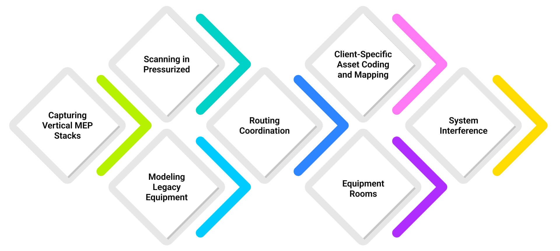
Capturing Vertical MEP Stacks
In high-rise buildings or hospitals, MEP risers are layered across 20–30 floors with minimal clearance. Scanning these shafts requires phased access coordination, confined-space protocols, and precise registration to avoid misalignment between levels.
-
Scanning in Pressurized
Pharmaceutical plants and cleanrooms operate under strict air control and access restrictions. Scanning workflows must align with gowning procedures, HEPA zone containment, and cleaning validations, limiting scanning hours and requiring clean-certified equipment.
-
Modeling Legacy Equipment
Many older systems lack nameplates, O&M manuals, or consistent tagging. When translating point clouds into FM-ready BIM, teams must perform onsite verification and reverse-identify systems based on line routing or service zones.
-
Routing Coordination
Facilities that combine retail, commercial, and hospitality spaces often have retrofitted MEP networks layered without prior documentation. Modeling these networks involves tracing inter-system overlaps and capturing deviations from original routing plans.
-
Client-Specific Asset Coding and Mapping
FM teams may use custom asset IDs, preventive task codes, or legacy hierarchy structures not aligned with industry BIM standards. Model output must be restructured to match internal CAFM configurations, which requires a translation layer or plugin-based export mapping.
-
Equipment Rooms
Facilities with 24/7 cooling, such as data centers or laboratories, cannot afford shutdowns. Scan teams must document mechanical rooms while systems are live, which limits the ability to isolate reflective surfaces, remove barriers, or reposition infrastructure.
-
System Interference
In environments with high electromagnetic interference or heavy thermal gain such as substations, boiler rooms, or rooftop units. Scanner accuracy and positioning can be affected. Additional survey control points and calibration steps are required to ensure model reliability.
Conclusion
MEP Scan to BIM supports facility operations by delivering verified spatial data that reflects the exact configuration of mechanical and electrical infrastructure within active zones. This model becomes the reference point for tasks that involve isolating floor-level shutoffs, confirming clearance before equipment replacement, and planning phased system upgrades without disrupting adjacent services. In complex environments such as healthcare campuses, clean manufacturing lines, or mission-critical data centers, the model supports alignment between facilities, engineering, and vendors using one coordinated dataset. With accurate system metadata linked to component geometry, the facility team gains control over maintenance timelines, risk thresholds, and future retrofit planning based on field-verified conditions.


Recent Comments