Structural deviations on-site can trigger a chain reaction of delays, cost escalations, and design conflicts across AEC projects. Whether it’s a misaligned column affecting façade installation or an uneven slab disrupting partition layouts, engineers are expected to catch these discrepancies early, often under compressed schedules and complex coordination environments. The need for precise validation before moving to downstream trades has made structural accuracy a non-negotiable priority on construction sites.
Scan to CAD services have emerged as a critical tool for structural engineers who need to verify built conditions against design intent. By capturing high-resolution 3D scans of structural elements, beams, cores, slabs, anchors and converting them into CAD or BIM formats, engineers can detect millimeter-level deviations that traditional surveying methods often miss. This process is especially valuable in shell-core construction, retrofit projects, and phased builds where accurate sequencing depends on verified as-builts.
Across the AEC sector, firms are integrating into QA/QC workflows to validate structure before issuing pour approvals, releasing fabrication drawings, or closing out subcontractor scopes. The ability to compare design models like IFC and DWG with real-world conditions at key milestones helps engineering teams prevent cascading errors, support contractual documentation, and deliver highly detailed outcomes in increasingly complex building environments.
What is Scan to CAD in the AEC Context?
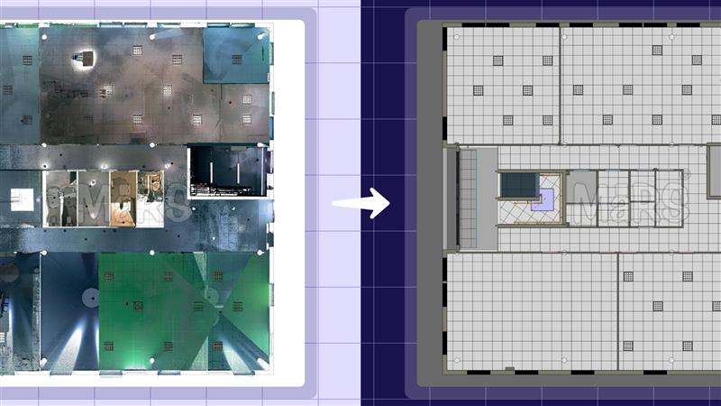
Scan to CAD, in real AEC engineering workflows, involves transforming 3D laser scan data captured from on-site structural elements like post-tensioned slabs, shear walls, or anchor layouts into construction-ready CAD or BIM files used for structural validation. Engineers rely on this method to assess discrepancies between design intent and actual built geometry during critical phases such as pre-slab pours, structural steel inspection, or concrete core verification. Unlike traditional surveys, this process captures high-density point cloud data and converts it into DWG, RVT, or IFC files that plug directly into coordination platforms. It ensures measurable, traceable validation of dimensional accuracy in environments where tolerance deviations of even 10–15 mm can trigger redesigns, RFIs, or installation delays.
- Converts 3D laser scans of beams, columns, slabs, and cores into DWG/RVT/IFC formats
- Used by structural engineers to validate layout before pour approvals or steel installation
- Supports elevation flatness mapping, embed plate positioning, and column shift detection
- Platforms: Autodesk Revit for modeling, Navisworks for clash validation, BIM 360 for scan processing
- Enables deviation overlay against IFC or structural drawing sets for QA/QC documentation
- Common in tower cores, podium decks, industrial mezzanines, and retrofit environments
- Provides site-verified models are ready for prefabrication planning or construction sequencing
Core Engineering Applications of Scan to CAD
As-Built Documentation
On multi-phase projects or fast-tracked builds, structural drawings often become outdated mid-construction. Engineers use to capture exact geometries of poured slabs, shear cores, and framing systems, ensuring as-builts reflect what’s truly in place before proceeding with coordination or compliance reporting.
Construction Verification & Structural Validation
Critical structural elements like embedded plates, steel columns, or PT slab profiles. It must align within tight tolerances. Engineers overlay scan-based CAD files on IFC models to identify shifts, deflections, or layout errors before sign-offs. This supports QA/QC at key milestones like pre-pour approvals or steel inspections.
Renovation & Retrofit Planning
When integrating new load-bearing systems or risers into existing facilities, engineers can’t rely on decades-old drawings. It provides verified geometries of existing conditions, allowing structural teams to plan interventions around real slab thicknesses, beam depths, and obstruction zones.
Reverse Engineering
For undocumented or poorly recorded industrial structures, It enables engineers to rebuild structural documentation from the ground up. This is often used before load upgrades, seismic retrofits, or compliance recertification, where precise geometry is a prerequisite.
Floor Flatness & Wall Plumb Analysis
Even minor floor slope variations can affect equipment installation, racking alignment, or partitioning. Engineers use scan-derived elevation maps and vertical section analysis to confirm floor and wall tolerances meet spec before handover or during interior fit-outs.
Prefabrication & Assembly Validation
Before shipping prefabricated staircases, MEP racks, or façade panels, engineers verify that on-site conditions match fabrication drawings. It ensures steel baseplates, concrete openings, and hanger inserts are correctly placed to avoid on-site clash or modification.
Digital Twin & Lifecycle Monitoring
Post-construction, engineers convert scan data into CAD/BIM-based digital twins to monitor long-term deflections, settlement, or fatigue. This is key in infrastructure, energy plants, and high-rise projects where structural health must be tracked across the lifecycle.
Heritage Structure Documentation
For structurally compromised heritage buildings, laser scanning captures geometry without physical contact. Engineers convert this into CAD to analyze leaning walls, out-of-plane facades, or decayed structural cores informing safe stabilization and preservation strategies.
Scan to CAD Workflow for Structure Validation
Planning & On-Site 3D Scanning
Engineers coordinate with site managers to schedule scanning between structural phases often after formwork removal but before MEP rough-ins. Scanning targets are defined based on tolerance-critical areas such as transfer slabs, elevator cores, and cantilevered beams. On complex sites, such as high-rise podiums or industrial mezzanines, multiple scanner positions are deployed to avoid occlusions from temporary props or scaffolding. Engineering teams verify that the captured spatial data aligns with structural gridlines and control benchmarks before approving for modeling.
Point Cloud Processing
Point clouds are registered using site-specific coordinates often tied to survey control points or existing Revit/IFC models. Engineers isolate structural systems from clutter and segment by construction sequence. This enables focused validation of each critical element. Misalignments between scan stations are corrected to sub-centimeter accuracy to ensure reliable geometric extraction, in high-tolerance environments like post-tensioned decks or steel assemblies.
CAD/BIM Modeling
Modelers extract precise geometry for core elements such as concrete profiles, steel framing, and embedded plates often prioritizing regions under design scrutiny or flagged in RFIs. The modeling is done to match drawing layer standards and export requirements for Navisworks clash checks or consultant overlays. For QA/QC workflows, elements like stair cores, slab drops, and edge forms are detailed to match field as-builts, not just generalized geometry. Deliverables are exported in DWG or RVT formats depending on the coordination platform.
Structural Comparison & Deviation Analysis
Once the CAD output is aligned with the design model, engineers use software tools to detect slab warping, column drift, or core misalignment beyond structural tolerances, typically ±10–15 mm. Automated deviation heatmaps and section-based variance reports are generated and reviewed with site teams to determine whether observed deviations require remediation or can be accepted with justification. These reports often serve as QA evidence during milestone approvals or to close out structural scopes.
Benefits for Engineering Teams
- Validates Structural Readiness Before Pour Approvals
Enables engineers to verify slab recesses, PT anchor zones, and sleeve layouts using scan-based CAD reducing risk of incorrect concrete placement and costly post-pour rectifications.
- Prevents Delay-Causing Structural Rework in Fast-Track Projects
Catches embedded item shifts or misaligned cores early, allowing corrections within the current cycle instead of triggering out-of-sequence rework later in the construction timeline.
- Quantifies Field Deviations with Engineering-Grade Reports
Delivers deviation maps and structural variance reports that quantify whether a column drift or slab camber is within accepted tolerance useful for technical sign-offs or contractor disputes.
- Aligns Prefab and On-Site Conditions with Millimeter Accuracy
Ensures fabricated stairs, façade brackets, or structural steel modules are delivered to verified field conditions avoiding site welding, adjustment, or part rejection.
- Improves Cross-Discipline Handover Between Structural and MEP
Confirms that structural penetrations, deck openings, and sleeves are placed correctly before releasing MEP installation minimizing coordination RFIs and ceiling space conflicts.
- Supports Structural Load Path Integrity in Retrofit Scenarios
Helps engineers assess slab thickness, beam dimensions, and wall alignments when retrofitting or adding load-bearing elements in older or undocumented structures.
- Reduces Risk Exposure in High-Rise and Critical Infrastructure Projects
Provides structural validation in environments where deviation tolerance is extremely tight such as elevator cores, seismic zones, or utility tunnels enhancing compliance and safety.
- Creates QA/QC Evidence for Third-Party Verification and Claims
Engineers can present scan-to-CAD overlays and deviation logs as part of their technical documentation for insurers, third-party verifiers, or dispute resolution.
- Allows Remote Review by Consultants Without Site Access
Scan-based CAD files enable off-site structural consultants or design leads to review actual field conditions in detail, without needing repeat site visits.
Field-Level Challenges
- Engineers often get a narrow scanning window between de-shuttering and duct riser setup leaving no room for rescan if alignment fails.
- Post-pour scanning often reveals embed plates or anchor bolts partially covered by concrete overpour, reducing scan clarity and affecting validation accuracy.
- Vertical stacking errors or core wall drift across levels complicate point cloud registration, making it harder to verify plumb alignment or tolerance compliance.
- Scan registration is frequently misaligned with Revit origin or design coordinate systems, requiring engineers to recalibrate scans before modeling.
- Scans captured in operational plants or boiler rooms suffer from thermal mirage, steam interference, or high-dust zones, compromising cloud fidelity.
- Field teams may scan full decks, but modelers are not briefed on critical validation zones, leading to unnecessary modeling effort and missed QA targets.
- Live sites often have trades working in adjacent zones, forcing engineers to compromise scanner placement resulting in incomplete captures or parallax gaps in vertical elements.
- Fabricators demand verified dimensions before deliverables are complete, forcing teams to choose between speed and accuracy on fast-track commercial interiors.
Pro Tip: Always scan around shear wall junctions and stair core landings before slab pour; these zones hide minor shifts that trigger major prefab misfits.
Why Engineers Choose Professional Scan to CAD Providers
Engineers partner with Scan to CAD specialists not just for modeling support, but to eliminate risk in high-tolerance, high-pressure structural environments. These providers understand when to prioritize core wall intersections over full-deck scans, how to align point clouds with shifting grid references across levels, and how to flag deviations that matter structurally. They’re brought in when internal teams face compressed pour cycles, undocumented retrofit zones, or prefab deadlines that can’t afford rework. With expertise in sequencing, multi-trade modeling, and tolerances down to 5 mm, they don’t just deliver files they close technical gaps between field conditions and design-critical approvals under real-world constraints.
Conclusion
Scan to CAD workflows bring structural validation into the fast-paced, error-sensitive reality of modern AEC execution. Engineers use it to measure structural precision where it impacts project flow the most—slab leveling before façade anchor placement, core wall alignment ahead of lift installation, or floor deviations prior to MEP rack handoffs. These services turn raw scan data into decision-ready models that support pour approvals, prefab release, and structural QA milestones. As projects grow in complexity and speed, engineering accuracy depends on field data that aligns precisely with design expectations. It enables that alignment clearly, efficiently, and with measurable impact on build quality and delivery certainty.


Recent Comments