
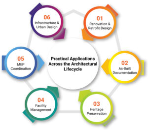
Architectural teams working on renovation, vertical expansion, or infrastructure tie-ins face a consistent obstacle: unreliable site data. Many existing buildings lack up-to-date documentation, and design decisions often rely on assumptions, outdated CAD files, or fragmented field notes. In fast-paced construction environments, this disconnect between real conditions and design input creates delays, coordination gaps, and costly change orders.
Scan to BIM has become a critical enabler for bridging this gap. By capturing site geometry through laser scanning and converting it into BIM-ready models, architects gain immediate access to accurate as-built data that aligns with construction tolerances. Architectural Scan to BIM Services supports this process by delivering geometry that reflects actual slab levels, wall cores, and service zones, allowing design teams to model directly over verified conditions for early clash prevention and tighter coordination with trades.
For firms engaged in design-build, phased construction, or retrofit-heavy scopes, integrating into the early design phase supports collaboration with contractors and fabricators. It reduces rework, accelerates schematic-to-DD transitions, and grounds architectural intent in real-world conditions, transforming it from a simple documentation upgrade into a true workflow advantage.
Why Scan to BIM Matters in the AEC Ecosystem
Scan to BIM, also known as Reality Capture to BIM, is a reality-capture-driven modeling method where verified site geometry is used to generate BIM models that align with construction-grade tolerances. For architectural firms working in renovation-heavy scopes, multi-phase retrofits, or tenant-in-place conditions, Reality Capture to BIM replaces assumption-based modeling with laser-verified data, allowing design teams to work from actual slab levels, core penetrations, and envelope geometry from day one. The result: cleaner coordination with engineers, fewer RFIs in construction, and reduced liability for design discrepancies.
Where it’s Used Most
- Interior reconfiguration in high-rise office retrofits with active tenant occupancy
- Façade realignment for cladding upgrades in aging corporate towers
- Structural tie-ins for podium-to-tower transitions in mixed-use developments
- MEP-intensive redesigns of existing labs, healthcare, or cleanroom facilities
- Roof elevation and structural grid alignment during vertical extensions
- BIM-ready as-built deliverables for handover compliance in EPC-led projects
Anchoring architectural modeling to scan-verified geometry boosts speed and precision in DD progression while eliminating survey dependency. This approach helps firms meet BIM Execution Plan standards from day one in design-build and integrated project delivery.
What is Scan to BIM and How Does It Work?
Scan to BIM is a reality-capture-driven modeling method where verified site geometry is used to generate BIM models that align with construction-grade tolerances. For architectural firms working in renovation-heavy scopes, multi-phase retrofits, or tenant-in-place conditions. It replaces assumption-based modeling with laser-verified data allowing design teams to work from actual slab levels, core penetrations, and envelope geometry from day one. The result: cleaner coordination with engineers, fewer RFIs in construction, and reduced liability for design discrepancies.
Technology Overview
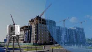
- Terrestrial Laser Scanners: Preferred in commercial interiors, complex structural cores, and tight-tolerance conditions.
- Handheld SLAM Systems: Used for fast mobility across live construction zones or partially occupied floors during phasing.
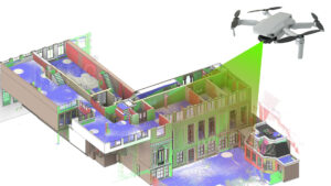
- Photogrammetry for Elevation Mapping: Supports exterior envelope modeling, roof slope validation, and heritage façade detail capture.
- Point Cloud File Types: Registered outputs such as .RCP, .E57 aligned with project north, structural grids, or survey benchmarks.
- BIM Modeling in Revit: Point clouds referenced as underlays or cut through for modeling floor-by-floor in architectural families, native to LOD targets.
Workflow
- Requirement Alignment: Define geometry scope (shell/core, interiors, structure), modeling use cases (coordination, demo planning), and target LOD (e.g., LOD 300 for core/shell, LOD 350 for FM handover).
- Scan Strategy and Site Logistics: Coordinate scanning sequence with GC, site access during off-hours, and required resolution for critical zones.
- Laser Scanning Execution: Capture performed with overlap across floors and controlled environments to minimize reflectivity and noise.
- Registration and Validation: Align scan sets across levels; perform QA against structural gridlines or control markers for dimensional accuracy.
- Modeling by Discipline Zones: Architectural shell, façade systems, and circulation modeled in separate linked files or segmented packages.
- Metadata and Classification Embedding: Assign wall types, level constraints, and property data to enable IFC export and QTO integration.
- Accuracy Cross-Check: Run point cloud-to-model variance checks using tolerance tools in Revit or Navisworks before releasing for coordination.
- Model Deployment: Load final models into the CDE like BIM 360 for structural, MEP, and contractor input.
Workflow Enhancements for Architecture Teams
Verified Geometry for Early Design Authoring
Architects modeling over scan data eliminate dependency on legacy DWGs or redlined PDFs. Slab edge verification, lift core geometry, and actual column offsets allow teams to begin design with the same dimensional baseline used by structural and MEP trades avoiding constant adjustments during DD or CD phases.
Real-Time Massing Feasibility over Complex Topographies
Scan to BIM allows architectural teams to overlay zoning envelopes, shadow studies, or floor plate test fits directly on terrain-accurate models. This replaces weeks of survey lag and supports faster planning submittals tied to real conditions, not assumed grades.
Model Structuring that Matches Contractor Coordination Packages
Architectural models created from scan data can be structured to align with construction sequencing such as splitting podium and tower cores, service zones vs shell zones. It enables clean handoffs to construction managers and reduces friction during trade coordination or Navisworks federation.
Improved Section Fidelity for Detail-Rich Schematic Sets
When scan-based BIM is used as a modeling base, wall chases, soffit drops, and slab steps are already represented in the geometry. This helps early section cuts shown to clients or design review boards reflect constructible conditions, reducing rework between SD and DD documentation sets.
Key Benefits for Architectural Firms
- Captures exact shaft-to-structure clearances critical for duct riser and stairwell planning
- Provides verified slab edge geometry for clean alignment with precast façade systems
- Supports wall and core placement tied to actual column grid drifts in retrofit structures
- Reduces RFIs related to undocumented slab recesses, dropped beams, or chase spaces
- Enables clash-free routing zones by modeling over true as-built MEP congestion
- Integrates geometry tolerances aligned with contractor coordination workflows (e.g., ±10mm)
- Allows architectural teams to generate sections that reflect field-level variation in floor elevations
- Eliminates over-modeling by focusing only on zones impacted by rework or redesign
- Supports phasing logic in renovation projects by distinguishing between retained and replaced geometry
- Improves alignment of stair cores and lift wells with structural cutouts based on existing geometry
Technical Workflow Integration Points
- Use scan-aligned grids to correct misaligned column lines in legacy structural cores
- Generate clean section boxes from point clouds for riser, corridor, and lobby modeling zones
- Match floor levels to actual elevation shifts captured in multi-slab or mezzanine conditions
- Segment scans by construction phase to reflect partial demolition or fit-out packages
- Overlay structural slab edges and existing MEP trunk lines for conflict-free soffit modeling
- Apply classification codes during modeling to align with spec-driven RFIs or bid set templates
Return on Investment for Architecture Firms
Scan to BIM increases ROI for architectural firms by directly reducing geometry-based coordination risks in existing-condition scopes. By anchoring core wall, slab edge, and façade geometry to scan data, design teams avoid cascading rework during BIM coordination with structural and MEP consultants. This upstream accuracy shortens DD-to-CD transition cycles, especially in occupied renovations or multi-phase infrastructure upgrades. Firms working in design-build or EPC-led projects also benefit from increased scoring during preconstruction due diligence, where scan-based models demonstrate readiness for early trade input, clash prevention, and digital handover compliance, translating into stronger technical credibility and fewer model revisions post-award.
Challenges and Solutions
Challenge: Inconsistent structural alignment across legacy floor plates during vertical extensions
Solution: Use scan control points aligned with structural grids to reconcile slab drift and column offsets floor-to-floor before modeling core elements
Challenge: Misleading ceiling plenum space due to undocumented MEP congestion in occupied zones
Solution: Capture ceiling voids with overhead scans or handheld SLAM to reveal clash-prone service corridors prior to ceiling layout modeling
Challenge: Irregular façade planes create complications in adaptive re-cladding or curtainwall system design
Solution: Use scan-based deviation analysis to extract true façade geometry and drive parametric surface modeling within Revit or Rhino workflows
Challenge: Stair and elevator cores do not align with original structural documentation in heritage retrofits
Solution: Model cores based on scan-derived shaft dimensions to support accurate routing of lifts, risers, and life safety elements
Challenge: Scan-based model fails downstream Navisworks or BEP validation due to improper segmentation
Solution: Structure models by trade-scope (shell, core, envelope) and embed phase metadata to comply with coordination workflows from day one
Challenge: Difficulty matching scan-derived geometry to IFC classification during export
Solution: Apply OmniClass or custom classification at the modeling stage using scan-tolerant geometry boundaries to maintain IFC compliance
Conclusion
Scan to BIM strengthens architectural control in projects where existing conditions define design constraints. It enables early modeling tied to real slab geometry, column grids, and vertical alignments critical in retrofit, expansion, and coordination-intensive scopes. Architecture teams gain clearer alignment with structural tolerances, faster integration into GC coordination packages, and cleaner transitions between design phases. As digital deliverables become a baseline expectation in renovation and lifecycle-focused projects, It supports earlier decision-making, fewer revisions, and models that hold up under construction and facilities review.


Recent Comments