Digital precision is now a baseline expectation in construction projects involving complex geometries, phased execution, and tight tolerances. Survey-grade data acquisition has moved beyond manual tape and total station methods, making way for laser scanning, LiDAR, and photogrammetry-based solutions that generate comprehensive spatial datasets. These technologies form the backbone of Reality Capture, enabling exact replication of built environments and providing the foundation for informed, model-based decision-making.
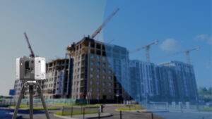
Reality Capture alone, however, does not meet the downstream needs of construction or facilities management without structured interpretation. That’s where Building Information Modeling becomes important for transforming raw point clouds into object-based, metadata-rich 3D environments. The RC-to-BIM pipeline comprises scanning, point cloud registration, model authoring, and validation. It offers measurable value in brownfield renovations, industrial retrofits, and as-built documentation, where precision and data continuity are non-negotiable.
This integrated workflow allows project teams to move from field data to intelligent models capable of supporting design coordination, clash detection, and lifecycle asset tracking. It mitigates assumptions in existing-condition modeling and replaces outdated 2D references with verifiable, traceable model elements. As regulatory standards and digital delivery mandates evolve, Reality Capture to BIM services has become a complex methodology for aligning physical conditions with virtual project environments, enabling speed, control, and traceability from preconstruction through facilities management.
Core Concepts & Foundations
Reality Capture
Reality Capture in AEC uses TLS, MMS, UAV photogrammetry, and LiDAR to collect high-density spatial data of built environments. Output formats like E57 and RCP are used in Revit or Navisworks workflows. Critical steps include geo-referenced scan planning, SLAM-based registration, and noise filtering to ensure model-ready accuracy for as-built documentation, clash validation, and phased construction.
Building Information Modeling
BIM enables data-rich modeling using classified elements like COBie with defined LODs 300–500. BIM objects drive quantity take-offs, 4D scheduling, and model-based coordination. Unlike CAD, BIM supports federated models across disciplines, aligning with ISO 19650 CDE workflows and enabling structured FM data handover.
Scan-to-BIM
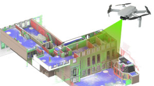
Scan-to-BIM converts registered point clouds into parametric models in Revit or IFC-based platforms. Used in retrofit, MEP coordination, and existing-condition validation, it supports model accuracy within LOA 30–40 standards. Typical deliverables include LOD 300 architectural shells, LOD 350 MEP systems, and COBie-enriched asset models for downstream use.
Workflow: From Site Scans to Smart Models
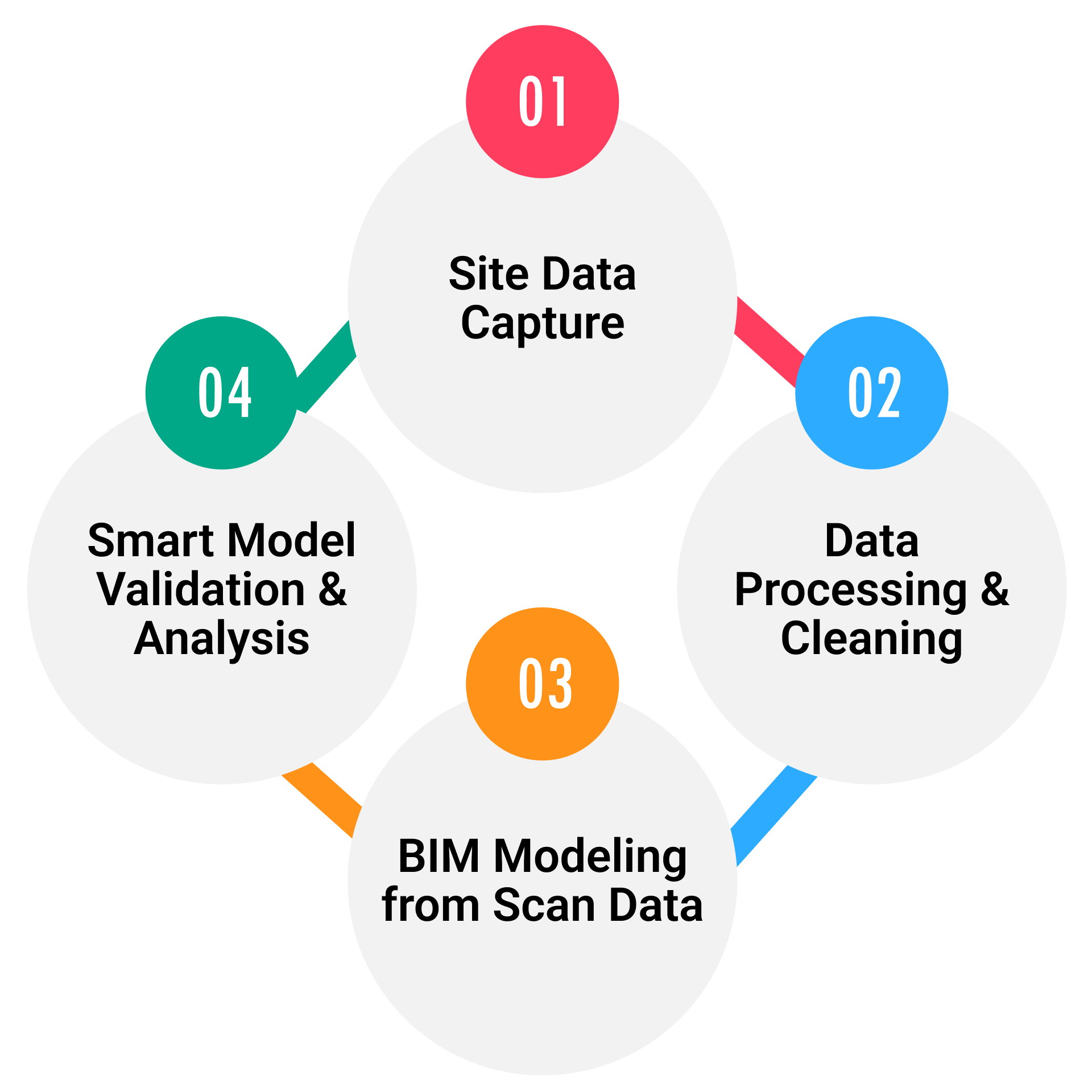
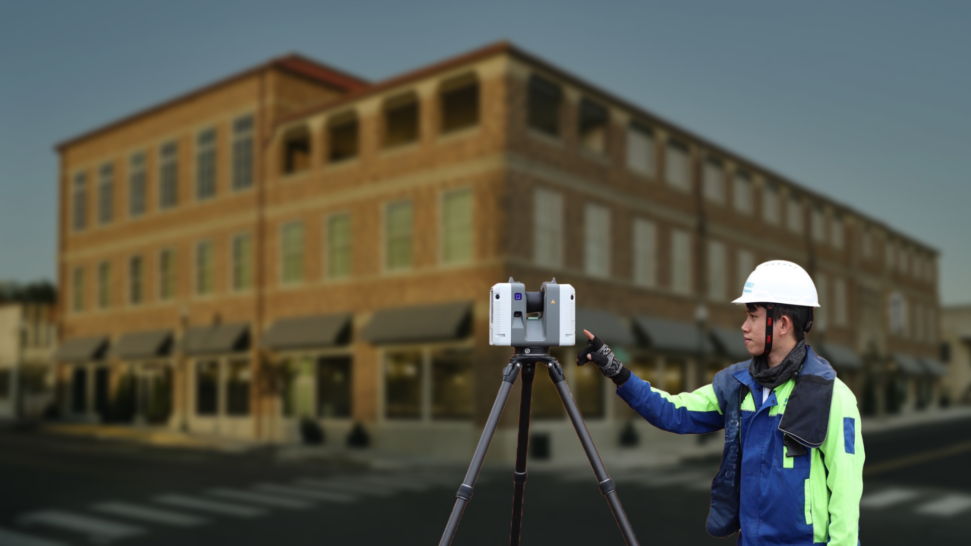
Site Data Capture
Scan scope is defined based on structural access, ceiling heights, and service zones. TLS like LiDAR and Leica RTC360 is deployed for interiors; drones handle exteriors or inaccessible façades. Scan control is established using survey benchmarks or BIM coordinate systems to ensure traceability in later modeling.
Data Processing & Cleaning
Raw scans are registered using Cyclone REGISTER 360 or FARO SCENE with accuracy targets below ±3mm. Noise from reflectivity errors or moving objects is removed, and point clouds are segmented by discipline or zone. Outputs are exported as RCS or E57 for Revit ingestion.
BIM Modeling from Scan Data
Revit is used to reconstruct architectural shells at LOD 300, structural framing with level-assigned parameters, and MEP elements with system classifications. Pipework, cable trays, and HVAC runs are modeled to match scan-tolerant geometry using detail lines as alignment guides. Classification is embedded using COBie and Uniclass tables.
Smart Model Validation & Analysis
Navisworks Manage runs clash tests between scanned MEP and new structural penetrations. Deviation checks using ClearEdge Verity or Revit point cloud tools flag geometry mismatches. Once verified, models are linked to 4D scheduling and 5D cost estimation platforms for timeline simulations and cost-loaded progress tracking.
Benefits of Reality Capture to BIM Integration
- Achieves ±2–3 mm spatial accuracy for retrofit-ready as-built conditions
- Enables early clash detection between scanned MEP and new structural insertions
- Reduces site walkdowns by up to 60% through scan-based remote coordination
- Facilitates Revit-based LOD 350–400 model creation aligned with scanned geometry
- Supports COBie-enriched asset tagging for FM integration in existing buildings
- Streamlines creation of 4D/5D-ready models for phased execution and budget control
- Allows QA validation against actual construction using Verity or Navisworks plugins
- Enables Digital Twin deployment with verified geometry and sensor-ready components
Scan-to-BIM vs Traditional As-Built Modeling
| Scan-to-BIM | Traditional As-Built Modeling |
| Uses geo-referenced point clouds like RCS, E57 from TLS or UAV systems | Relies on manual redlines, tape measurements, and outdated drawings |
| Supports ±3mm tolerance verification with tools like Verity or Cloud Compare | No precise deviation control; validation depends on field observation |
| Enables precise equipment pad and embed coordination in retrofit plants | Inaccurate placement often leads to on-site MEP misalignment |
| Captures above-ceiling utilities and hidden conditions with scan detail | Limited visibility requires ceiling access or destructive investigation |
| Produces LOD 350 models aligned with actual geometry for phased retrofits | Often rebuilds base plans from assumptions or legacy 2D drawings |
| Allows pre-install clash detection using real-world geometry in Revit/Navisworks | Clashes discovered during installation, requiring costly change orders |
| Supports COBie-tagged elements for handover into FM systems or Digital Twins | Output remains disconnected from FM systems and lacks asset data |
| Used in live hospitals and pharma labs without disrupting operations | Risk of operational downtime due to unknown or unverified conditions |
Challenges & Best Practices
- Use of full-resolution point clouds in Revit leads to lag and crashes; linking segmented RCS files with crop regions improves model performance.
- Misalignment in scan registration often results from reflective surfaces or lack of overlap; combining targets with SLAM-based alignment ensures stability.
- Exported scan data fails to align with IFC models due to inconsistent coordinate systems; aligning shared reference points during pre-scan avoids rework.
- Scan technicians deliver raw data without modeling context; tagging scan zones and noting system boundaries streamlines downstream modeling.
- MEP contractors request LOD 400 models, but input scans lack sufficient clarity; early agreement on achievable LOD/LOA avoids scope mismatches.
- BIM models pass QA but fail onsite verification; deviation checks using Navisworks or Verity must be embedded in the QA pipeline before issue release.
- Ceiling scans often exclude congested risers or flexible services; capturing multi-pass vertical scans or supplemental handheld scans ensures full coverage.
Conclusion
Reality Capture to BIM provides measurable control in scenarios like MEP-heavy retrofits, phased infrastructure upgrades, and plant revamps where dimensional accuracy and existing-condition fidelity are non-negotiable. With ±3mm scan precision, LOD 350–400 Revit modeling, and classification-ready outputs for COBie or IFC workflows, this pipeline eliminates guesswork in design coordination and asset verification. If you’re managing a project with tight tolerances, outdated drawings, or FM integration needs, we deliver targeted scan-to-BIM services from scope-specific model extraction to deviation checks and handover-ready outputs aligned to ISO 19650 standards.


Recent Comments